 |
Search Saab9000.com

|
| Procedures |
How to repair the headlight beam control relay |
|
|
By John Carlyle-ClarkeIntroductionIf you have problems with your headlights such as being always or sometimes unable to switch from low-beam to high-beam or vice-versa, or the headlights switching themselves from one to the other, then a prime suspect is the beam control relay, which suffers a lot from dry joints. Another possibility not discussed here is the column stalk switch which has been known to give problems, although less frequently than the relay. You can remove and repair this relay - this is an attractive options because a new one costs around £90 from Saab, although a more cost-effective alternative is now available. The worst that will happen is that you break it and have to buy a new one anyway. [Editor's note] Similar problems may also be caused by the
bulb-check relay, which is the orange relay in the photograph below.
This suffers from the same dry-joint problem and may be repaired in the
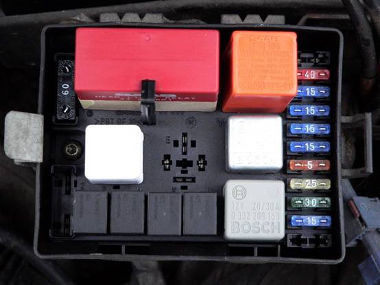
same way. ProcedureThe relay is located in the relay/fuse box in the engine bay near the battery.
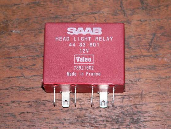
The relay in question is the large red one in the top left. Here it is in close up.
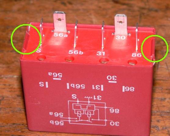
For me the hardest part was opening the case. There are two
clips which must be levered back simultaneously. I have done two and
have damaged the case a little both times, although it was nothing that
can’t be fixed. It was easier with two people with a screwdriver each.
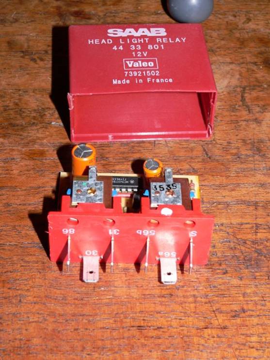
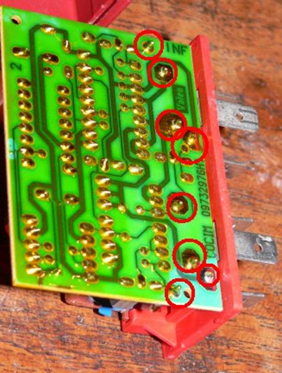
The clips are shown here: Once you get the clips released, the innards just slide out. Now you need to identify the problem joints. They are mainly the ones which connect to the spade terminals which plug into the relay box. When I looked at this relay under a scope at work, to be honest all the joints were pretty poor, and I redid lots of them. When I did my mother’s car, I just did the spade connector joints and the results were the same. I’ve highlighted the joints here which seem to be the worst.
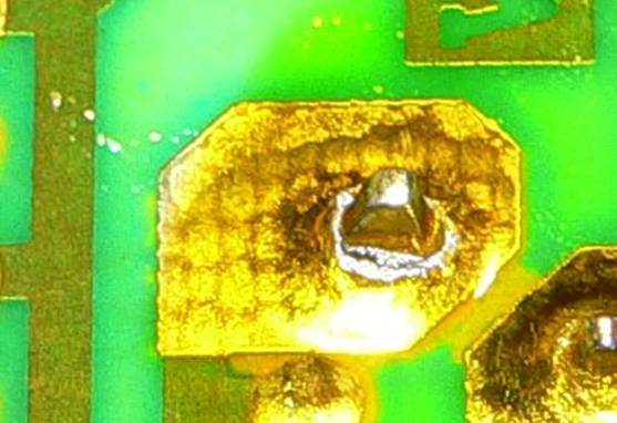
Here is a closeup of one of the dry-joints, so that you know what to look for.
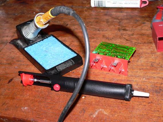
At this point you have two options, depending on your toolkit and your patience/obsessiveness. You can either use an iron and some solder and reheat these joints while applying a bit more solder, or you can go a bit further to get a better joint. I’ll describe the second method, as that is what I did. In addition to an iron and some solder, you’ll need a desoldering pump or some desoldering wick.
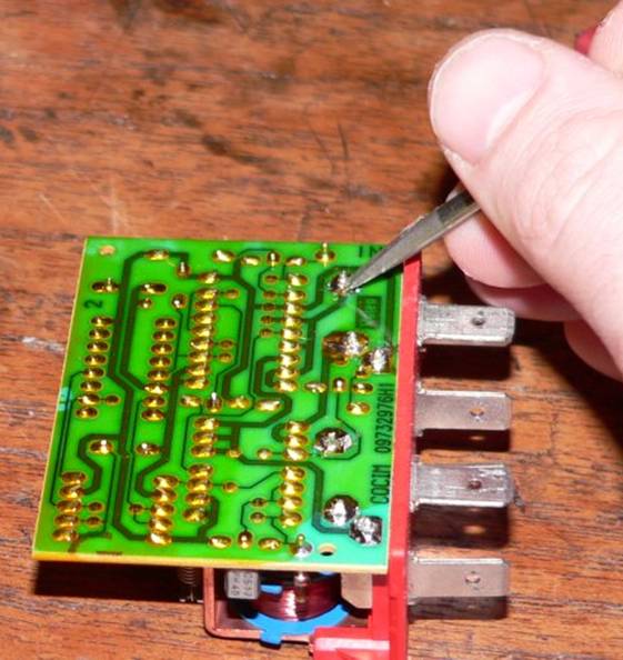
For each of the bad joints, I removed the solder with the pump and then attempted to clean the metal pin by scraping.
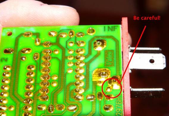
After this, I resoldered the joint. When viewed under the scope this method gave much better results. Whichever method you choose, make sure the tip of your iron is clean (use a damp sponge to clean it) and be careful not to create any shorts. There is one particular danger area where the pads are very close:
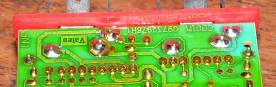
In the end you should have nice clean solder joints.
Pop the innards back into the case, making sure that clips engage. The first one I did, the case split up one of the edges, so I used some superglue on it after putting the innards in, wrapping some tape around the base to pull it together and keep the clips tight. On the second one, the damage was minor, but I put some tape on anyway. After all, who cares what it looks like, right?
Put the relay back in the box, and test that everything works as expected. If you have problems, the most likely cause is a short on the board, so you’ll have to take the case off again and check your work, with a magnifier if need be. |

|
|
| saab9000.com is an enthusiast's web site
and is not in any way affiliated with Saab Automobile. A big "thank
you" to Saab for producing the 9000. All information is presented in good faith. However, I am not a trained mechanic, just an enthusiast.Therefore, it is your responsibility to ensure that you are competent to carry out any procedures presented here and that they are correct. No responsibility can be accepted for any inaccuracies or consequential loss, injury or damage. |
Copyright © 2001-2013 Bill Jones |