 |
Search Saab9000.com

|
| Procedures | Repairing the Saab 9000 ECU |
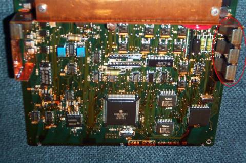
By SaabbenNoteThis procedure was carried out on a 1997 Saab 9000 Aero. I expect there will be no differences between this and other post-93 cars with the Trionic engine management system. This procedure will not apply to the 3.0 v6, light pressure turbos without a boost performance control solenoid valve or any pre-'93 cars with the APC system. IntroductionMost post-93 9000s employ Saabs own Trionic engine management system together with a boost performance control solenoid valve (AKA BPC Solenoid) to control turbo boost. The ECU sends a sinusoidal waveform to the boost control solenoid which in turn opens the waste gate via the waste gate actuator to limit boost. Due to the BPC Solenoid being a mechanical device, it is prone to wear and occasionally the solenoid will jam which normally causes one of two of the coils inside it to burn out and short circuit. In this case, fuse 5 in the fuse box will blow to protect the ECU however; I and others have discovered this is not always the case. I first discovered the problem when my car was not boosting much over the basic boost pressure (some have also found that the car will continually over-boost) and after some investigation I discovered that fuse 5 had blown. I replaced the fuse, which blew again within a short period of time, which pointed me to the BPC Solenoid. I purchased a new solenoid, replaced the fuse and checked that it was humming on ignition which it was. Shortly after I did this however I noticed that fuse 5 had blown again. I tested the resistance between the pins on the BPC Solenoid (circa 3 ohms between pins 1-2, and the same between pins 2-3) and confirmed that one of the coils had short circuited. I discovered later that the reason the ECU had blown the second BPC
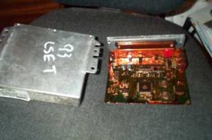
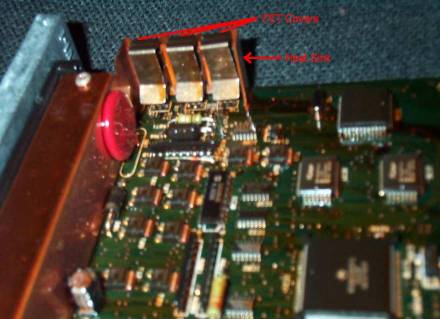
Solenoid was because one of the three MOSFETs in the ECU which control
the BPC solenoid was damaged (due to fuse 5 not protecting it?) and
instead of supplying a sine wave was just supplying ~ -13v which burnt
out one of the coils very soon after the ignition was switched on. The
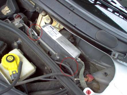
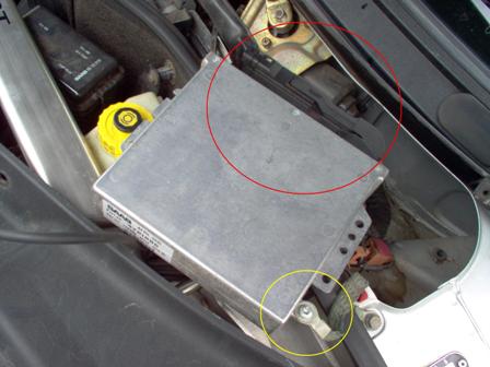
below procedure is how I repaired the ECU in my car to restore the Time requiredIncluding removing and reinstalling the ECU in to the car, the job should take about 45-75 minutes to complete. Tools requiredTo remove the ECU from the car
To repair the ECU
Procedure
Thanks go out to Scaero who supplied the pictures of the inside of the ECU. |
![[fawlty]](images/image001.gif) which
I so sorely missed!
which
I so sorely missed!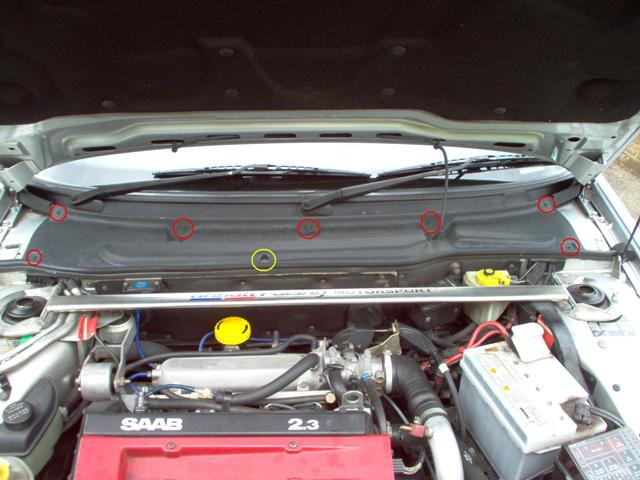

|
|
| saab9000.com is an enthusiast's web site
and is not in any way affiliated with Saab Automobile. A big "thank
you" to Saab for producing the 9000. All information is presented in good faith. However, I am not a trained mechanic, just an enthusiast.Therefore, it is your responsibility to ensure that you are competent to carry out any procedures presented here and that they are correct. No responsibility can be accepted for any inaccuracies or consequential loss, injury or damage. |
Copyright © 2001-2013 Bill Jones |